Microwave guiding of electrons

For the first time scientists at Max Planck Institute in Germany have achieved guiding of electrons by purely electric fields.
The investigation of the properties of electrons plays a key role for the understanding of the fundamental laws of nature. However, being extremely small and quick, electrons are difficult to control. Physicists around Dr. Peter Hommelhoff, head of the Max Planck Research Group “Ultrafast Quantum Optics” at the Max Planck Institute of Quantum Optics (Garching near Munich), have now demonstrated efficient guiding of slow electrons by applying a microwave voltage to electrodes fabricated on a planar substrate (Physical Review Letters, Advance online publication, 9 May 2011). This new technique of electron guiding – which resembles the guiding of light waves in optical fibres – promises a variety of applications, from guided matter-wave experiments to non-invasive electron microscopy.
Electrons have been the first elementary particles revealing their wave-like properties and have therefore been of great importance in the development of the theory of quantum mechanics. Even now the observation of electrons leads to new insight into the fundamental laws of physics. Measurements involving confined electrons have so far mainly been performed in so-called Penning traps, which combine a static magnetic field with an oscillating electric field.
For a number of experiments with propagating electrons, like interferometry with slow electrons, it would be advantageous to confine the electrons by a purely electric field. This can be done in an alternating quadrupole potential similar to the standard technique that is used for ion trapping. These so-called Paul traps are based on four electrodes to which a radiofrequency voltage is applied. The resulting field evokes a driving force which keeps the particle in the centre of the trap. Wolfgang Paul received the Nobel Prize in physics for the invention of these traps in 1989.
For several years by now scientists realize Paul traps with micro structured electrodes on planar substrates, using standard microelectronic chip technology. Dr. Hommelhoff and his group have now applied this method for the first time to electrons. Since the mass of these point-like particles is only a tenth of a thousandth of the mass of an ion, electrons react much faster to electric fields than the rather heavy ions. Hence, in order to guide electrons, the frequency of the alternating voltage applied to the electrodes has to be much higher than for the confinement of ions and is in the microwave range, at around 1 GHz.
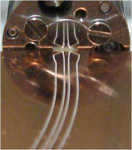
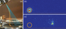
In the experiment electrons are generated in a thermal source (in which a tungsten wire is heated like in a light bulb) and the emitted electrons are collimated to a parallel beam of a few electron volts. From there the electrons are injected into the “wave-guide”. It is being generated by five electrodes on a planar substrate to which an alternating voltage with a frequency of about 1 GHz is applied (see Figure 1). This introduces an oscillating quadrupole field in a distance of half a millimetre above the electrodes, which confines the electrons in the radial direction. In the longitudinal direction there is no force acting on the particles so that they are free to travel along the “guide tube”. As the confinement in the radial direction is very strong the electrons are forced to follow even small directional changes of the electrodes.

“With this fundamental experiment we were able to show that electrons can be efficiently guided be purely electric fields”, says Dr. Hommelhoff. “However, as our electron source yields a rather poorly collimated electron beam we still lose many electrons.” In the future the researchers plan to combine the new microwave guide with an electron source based on field emission from an atomically sharp metal tip. These devices deliver electron beams with such a strong collimation that their transverse component is limited by the Heisenberg uncertainty principle only.
Under these conditions it should be feasible to investigate the individual quantum mechanical oscillations of the electrons in the radial potential of the guide. “The strong confinement of electrons observed in our experiment means that a “jump” from one quantum state to the neighbouring higher state requires a lot of energy and is therefore not very likely to happen”, explains Johannes Hoffrogge, doctoral student at the experiment. “Once a single quantum state is populated it will remain so for an extended period of time and can be used for quantum experiments.” This would make it possible to conduct quantum physics experiments such as interferometry with guided slow electrons. Here the wave function of an electron is first split up; later on, its two components are brought together again whereby characteristic superpositions of quantum states of the electron can be generated. But the new method could also be applied for a new form of electron microscopy.
More information: J. Hoffrogge, et al. Microwave Guiding of Electrons on a Chip, Physical Review Letters, Advance Online Publication, May 9, 2011. DOI:10.1103/PhysRevLett.106.193001
Abstract
We demonstrate the transverse confinement and guiding of a low energy electron beam of several electron volts in a miniaturized linear quadrupole guide. The guiding potential is generated by applying a microwave voltage to electrodes fabricated on a planar substrate, which allows the potential landscape to be precisely shaped on a microscopic scale. We realize transverse trapping frequencies of 100 MHz and guide electrons along a circular section of 37 mm length. A detailed characterization of the guiding properties in terms of potential depth and dynamic stability is given. This new technique of electron guiding promises various applications in guided matter-wave experiments such as electron interferometry.
Provided by Max Planck Institute


